Instruction - ModR/M Byte
About
The ModR/M byte is a part of an instruction used when a memory operand is required (used).
It permit to specify:
- the location of the first operand (address mode or register)
- and
- the location of the second operand (a register) if required by the instruction.
- or an extra bit for the opcode (opcode extension)
Articles Related
Syntax
Below is a picture of an intel instruction format (From appendix b instruction formats and encodings) where you can see the ModR/M field.
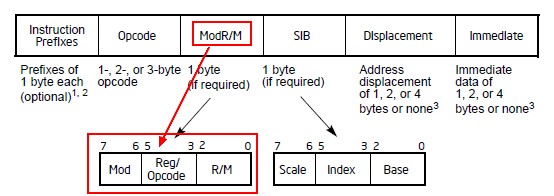
Certain encodings of the ModR/M byte require a second addressing byte (the SIB byte).
Table
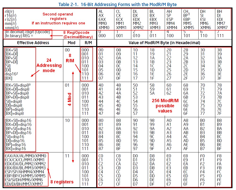
ModR/M byte has <math> 2^8 = 256</math> possible values by CPU word size (16, 32, … bit): seen under the label Value of ModR/M Byte (in Hexadecimal) in the tables called Addressing form table. There is actually one table by CPU Word Size (ie 16-bit or 32-bit)
Example with the table in 16-bit addressing forms (Section 2.1.5 - Page 509 of the Intel® 64 and IA-32 Architectures Software Developer’s Manual
The figure below demonstrates the interpretation of one ModR/M value. Example for C8.
ModR/M value       C8  = 11001000
                   ----------------
                   Mod = 11
                   RM  =      000
/digit (Opcode) or REG =   001
First operand
The Effective Address column lists 32 effective addresses and one of them is assigned to the first operand of an instruction.
See also: Memory Segment - Offset - (Relative|Effective) address.
The selection of an Effective Address is made by using the combination of:
The Mod field, or modifier field combined with rm field gives a total of <math>5</math> bits of information to specify (encode) <math>2^5 = 32</math> possible values:
- 24 addressing modes. The first 24 lines. They provide ways of specifying a memory location)
- 8 registers. The last eight (Mod = 11B) are for each line a list of 5 register (general-purpose, MMX technology and XMM registers). The register selected is determined by the opcode byte along with the operand-size attribute.
For example: The row indicated by:
- Mod = 11,
- R/M = 000.
identifies multiple registers in the effective address column:
- the general-purpose registers EAX, AX or AL;
- MMX technology register MM0;
- or XMM register XMM0.
The register selected is determined by the opcode byte along with the operand-size attribute.
Reg/Opcode
The Reg/Opcode field encodes either:
- a second register operand If an instruction requires it.
- or extends the Opcode field with 3 more bits. In cases where the reg/opcode field in the ModR/M byte represents an extended opcode, valid encodings are shown in Appendix B.
Second operand
If the instruction requires a second operand, the seventh row (labeled “REG =”) specifies the use of the 3-bit regopcode field when the field is used to give the location of a second operand that must be a register (general purpose, MMX technology, or XMM)
Rows one through five list the registers. The register selected is determined by:
- the opcode byte
- along with the operand-size attribute.
Opcode extension
If the instruction does not require a second operand, then the regopcode field may be used as an opcode extension. This use is represented by the sixth row in the tables (labeled “/digit (Opcode)”). Note that values in row six are represented in decimal form.
disp
- The disp16 nomenclature denotes a 16-bit displacement that follows the ModR/M byte and that is added to the index.
- The disp8 nomenclature denotes an 8-bit displacement that follows the ModR/M byte and that is sign-extended and added to the index.