Linear Algebra - Image representation
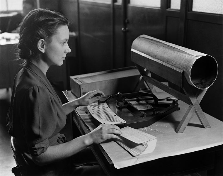
About
A generalized image consists of a grid of generalized pixels, where each generalized pixel is a quadrilateral (not necessarily a rectangle).
Think of an image as a grid of rectangles, each assigned a color. (The rectangles correspond to the pixels.) Each such rectangle in the image corresponds to a parallelogram in the plane.
In order to manipulate image in Linear Algebra, we need to represent images as matrices. We represent an image by a set of colored points in the plane.
Articles Related
Colored points
To represent a colored point, we need to specify its location and its color. We will therefore represent a point using two vectors:
- the location vector with labels {'x','y','u'}
- and the color vector with labels {'r','g','b'}.
The location vector represents the location of the point in the usual way|as an (x, y) pair. The u entry is always 1 (homogeneous coordinates are used to perform a translation).
For example, the point (12, 15) would be represented by the vector Vec({'x','y','u'}, {'x':12, 'y':15, 'u':1}.
The color vector represents the color of the point: the 'r', 'g', and 'b' entries give the intensities for the color channels red, green, and blue. For example, the color red is represented by the function {'r': 1}.
Scheme for representing images
Ordinarily, an image is a regular rectangular grid of rectangular pixels, where each pixel is assigned a color. Because images are transformed, a slightly more general representation is needed.
A generalized image consists of a grid of generalized pixels, where each generalized pixel is a quadrilateral (not necessarily a rectangle).
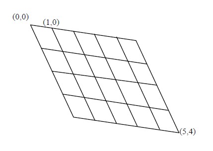
The points at the corners of the generalized pixels are identi ed by pairs (x, y) of integers, which are called pixel coordinates. The top-left corner has pixel coordinates (0,0), the corner directly to its right has pixel coordinates (1,0), and so on.
For example, the pixel coordinates of the four corners of the top-left generalized pixel are (0,0), (0,1), (1,0), and (1,1).
Each corner is assigned a location in the plane, and each generalized pixel is assigned a color. The mapping of corners to points in the plane is given by a matrix, the location matrix. Each corner corresponds to a column of the location matrix, and the label of that column is the pair (x, y) of pixel coordinates of the corner. The column is a {'x','y','u'}-vector giving the location of the corner. Thus the row labels of the location matrix are 'x', 'y', and 'u'.
The mapping of generalized pixels to colors is given by another matrix, the color matrix. Each generalized pixel corresponds to a column of the color matrix, and the label of that column is the pair of pixel coordinates of the top-left corner of that generalized pixel. The column is a {'r','g','b'}-vector giving the color of that generalized pixel.
For example, the image ![]() consists of four generalized pixels , comprising a total of nine corners.
This image is represented by:
consists of four generalized pixels , comprising a total of nine corners.
This image is represented by:
- the location matrix (which gives the location of columns in terms of v in a default coordinate system)
| v | (0,0) | (0,1) | (0,2) | (1,2) | (1,1) | (1,0) | (2,2) | (2,0) | (2,1) |
|---|---|---|---|---|---|---|---|---|---|
| x | 0 | 0 | 0 | 1 | 1 | 1 | 2 | 2 | 2 |
| y | 0 | 1 | 2 | 2 | 1 | 0 | 2 | 0 | 1 |
| u | 1 | 1 | 1 | 1 | 1 | 1 | 1 | 1 | 1 |
- and the color matrix (which gives the colors of a pixel per corner)
| (0, 0) | (0, 1) | (1, 1) | (1, 0) | |
|---|---|---|---|---|
| b | 225 | 125 | 75 | 175 |
| g | 225 | 125 | 75 | 175 |
| r | 225 | 125 | 75 | 175 |
By applying a suitable transformation to the location matrix, we can obtain
| v | (0,0) | (0,1) | (0,2) | (1,2) | (1,1) | (1,0) | (2,2) | (2,0) | (2,1) |
|---|---|---|---|---|---|---|---|---|---|
| x | 0 | 2 | 4 | 14 | 12 | 10 | 24 | 20 | 22 |
| y | 0 | 10 | 20 | 22 | 12 | 2 | 24 | 4 | 14 |
| u | 1 | 1 | 1 | 1 | 1 | 1 | 1 | 1 | 1 |
which, combined with the unchanged color matrix, looks like this: ![]()
Perspective
The perspective of an image is given by the notion of coordinate system.
Making a perspective-free image is just a translation from one coordinate system to the other. This translation function maps pixel coordinates from the first coordinates system to the coordinates of the corresponding point in the second coordinates system.
The basic approach to derive this mapping is by example. We get:
- several input-output pairs|points in the original coordinate system
- corresponding points in the target coordinate system
in order to derive the function that agrees with this behaviour.
At the heart of this mapping function is a change of basis.